Free Shipping over $35*

HLO Lighting

Permanent Lighting System | 60m (197 ft) Kit

SKU: PRML-KIT-60WH

$1,999.99

In stock and ready to order

Installer pricing available
Sign in or apply for an account.
Trim Color: White9 options

Minimum 1 · Order in increments of 1

Local pickup availability

HLO Lighting Warehouse: Available

Product information

Details and specifications

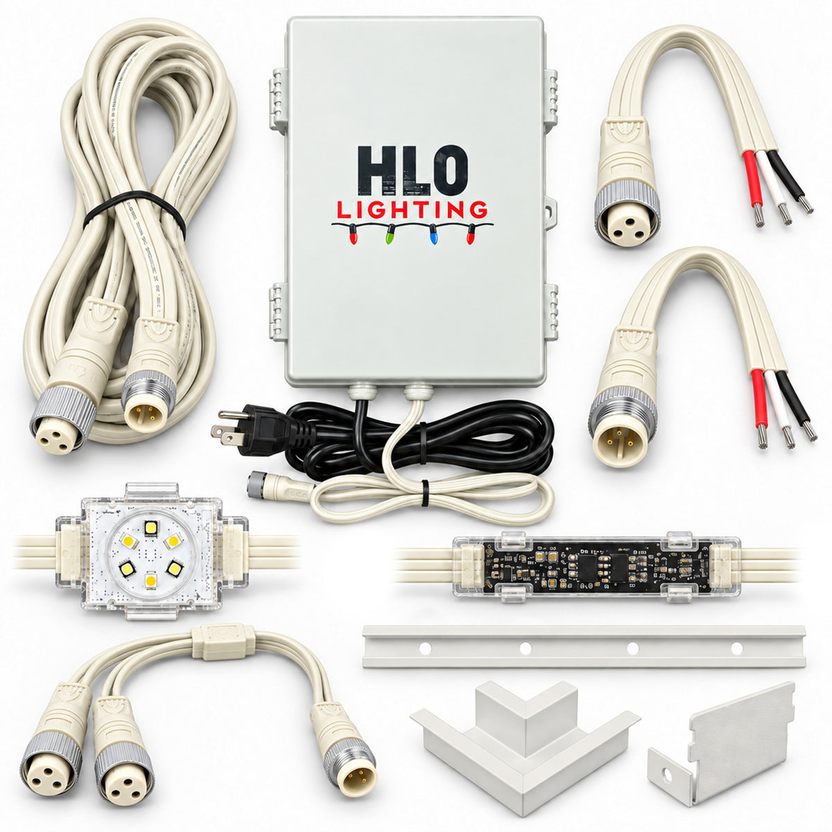
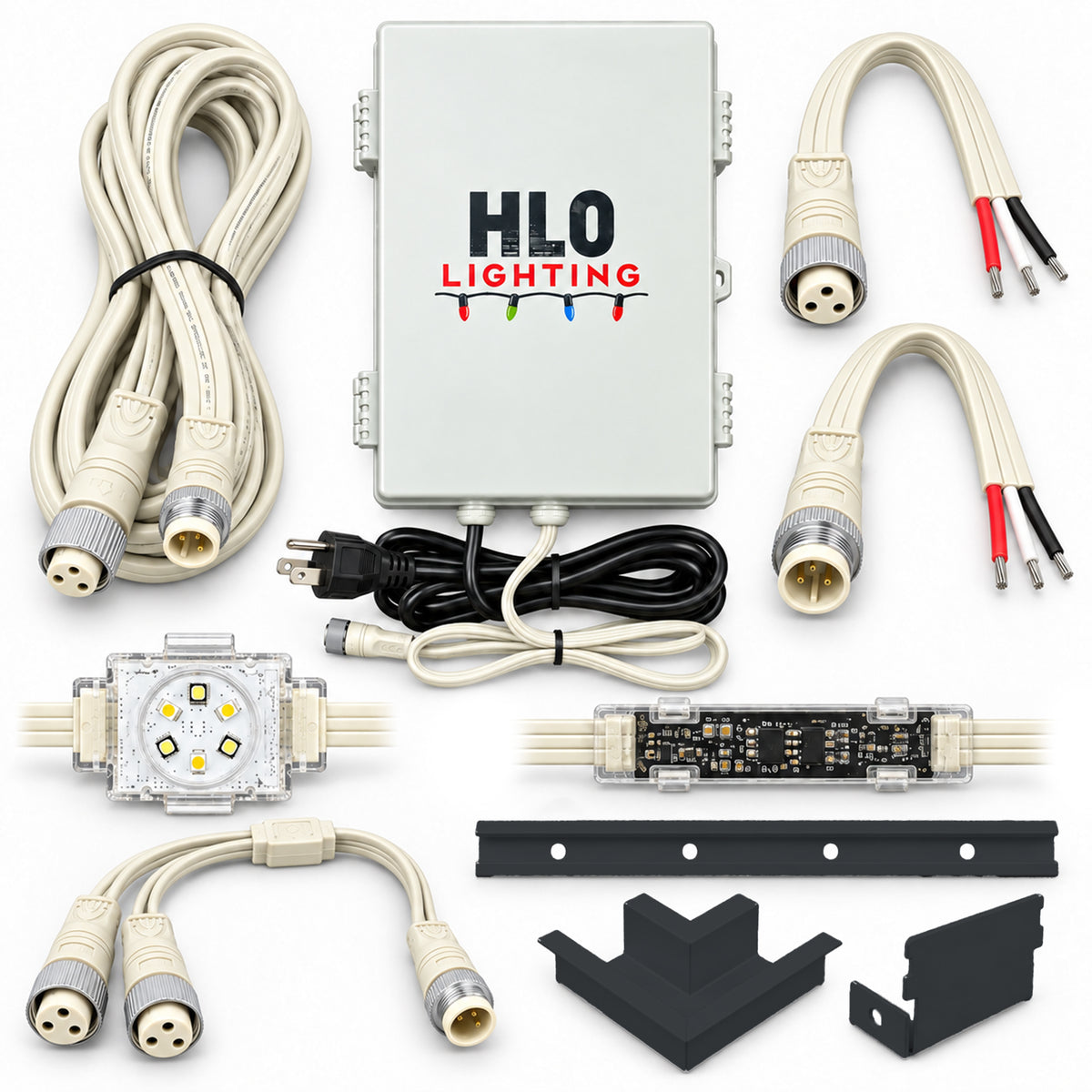
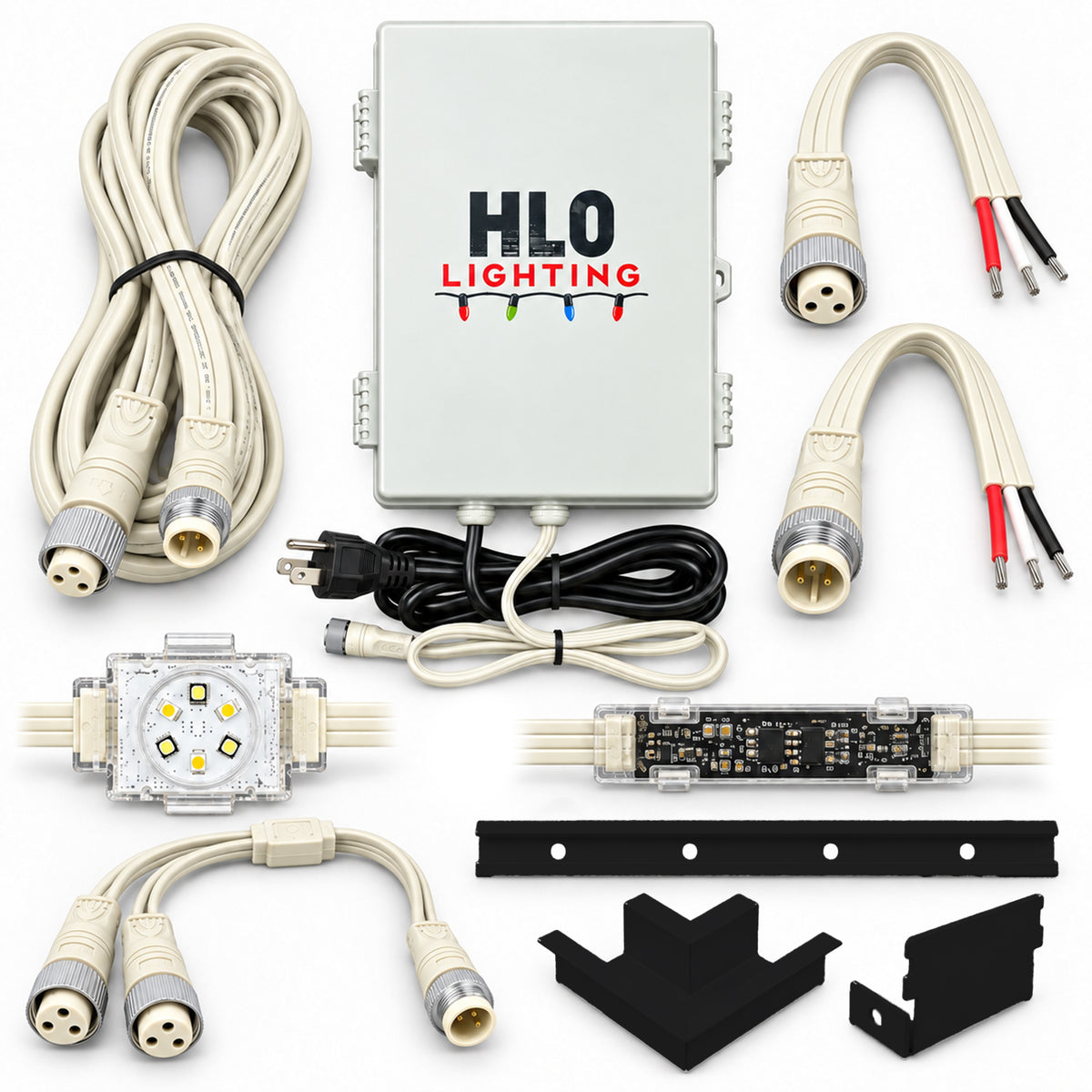
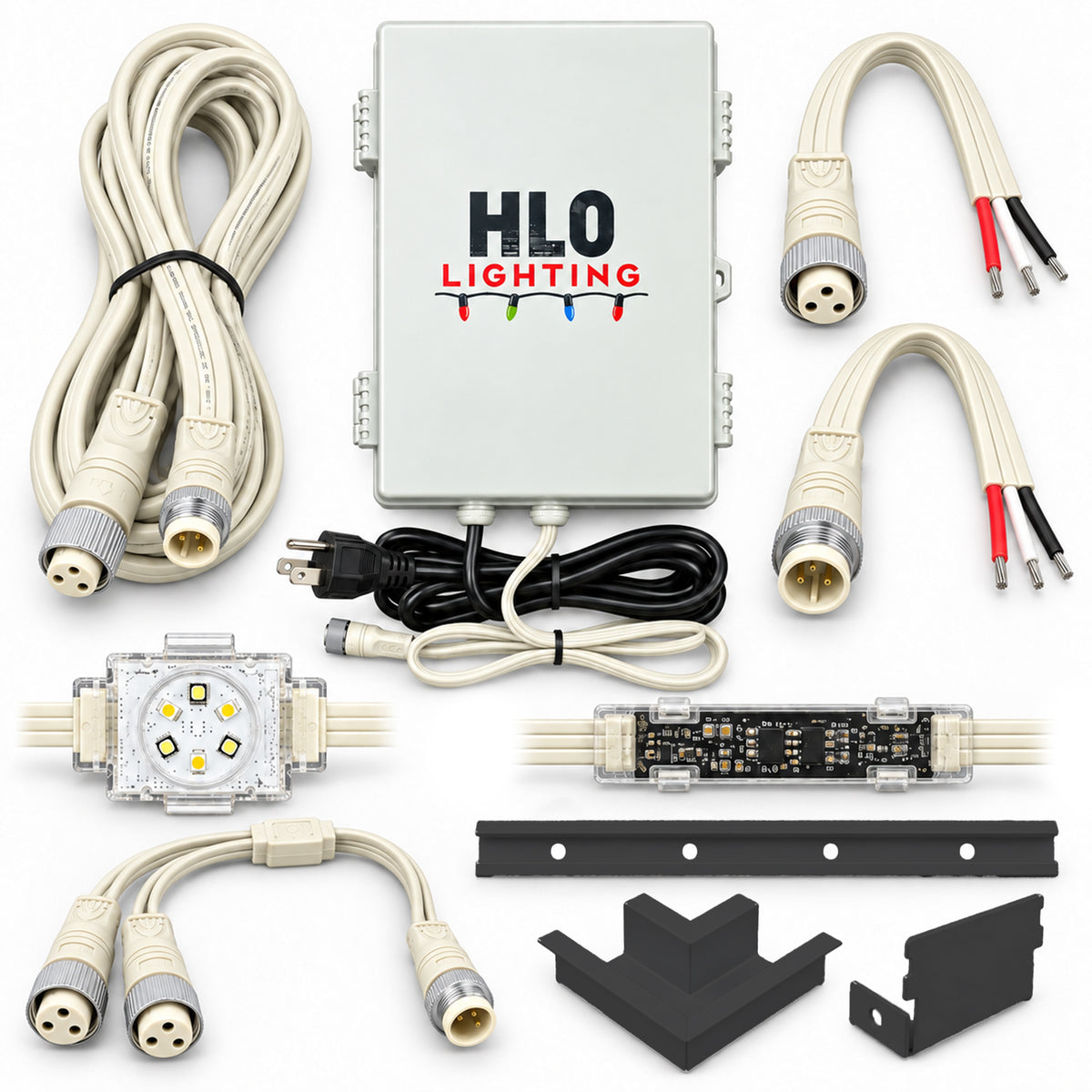
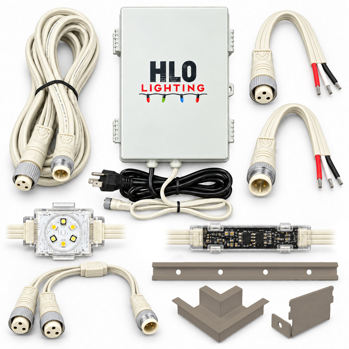
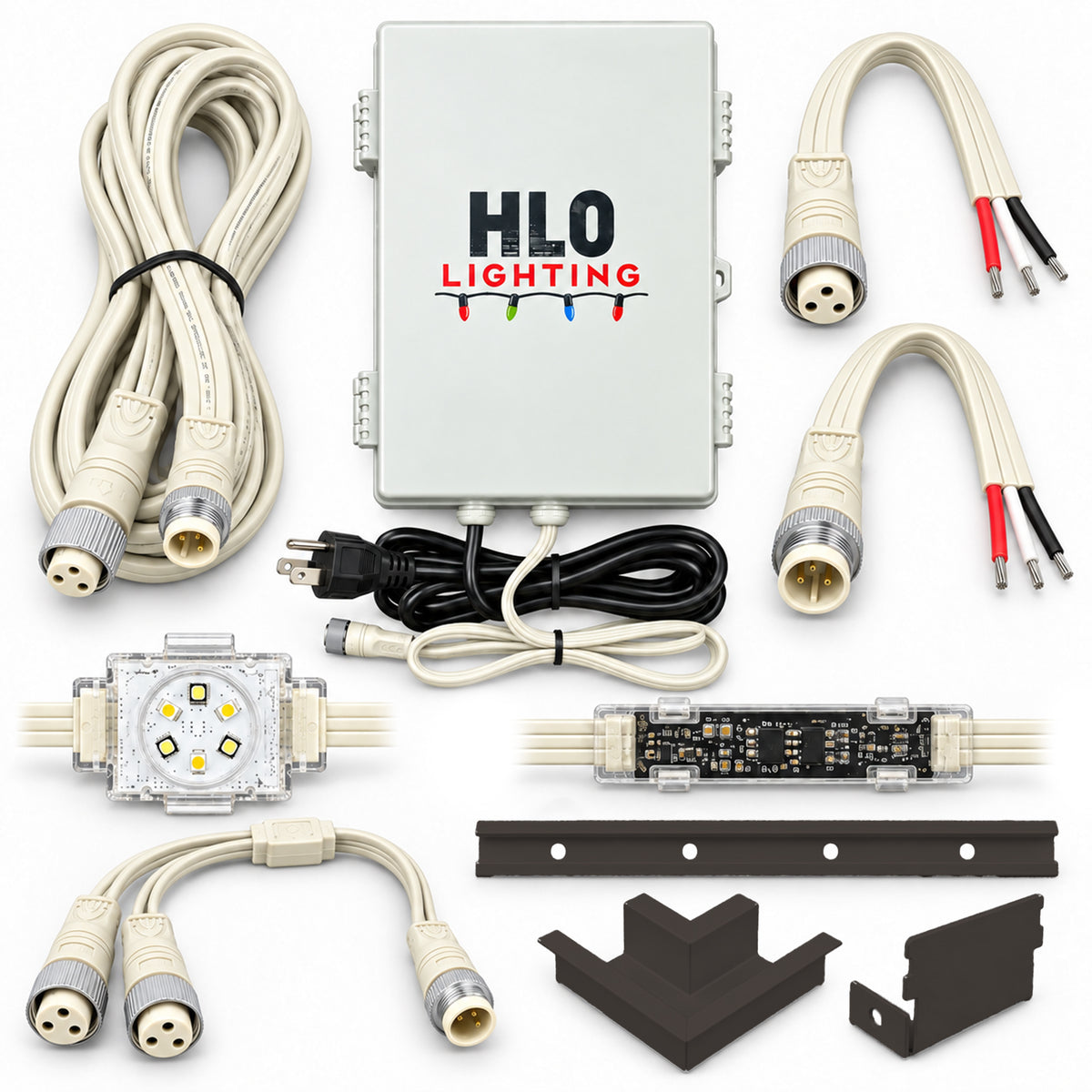
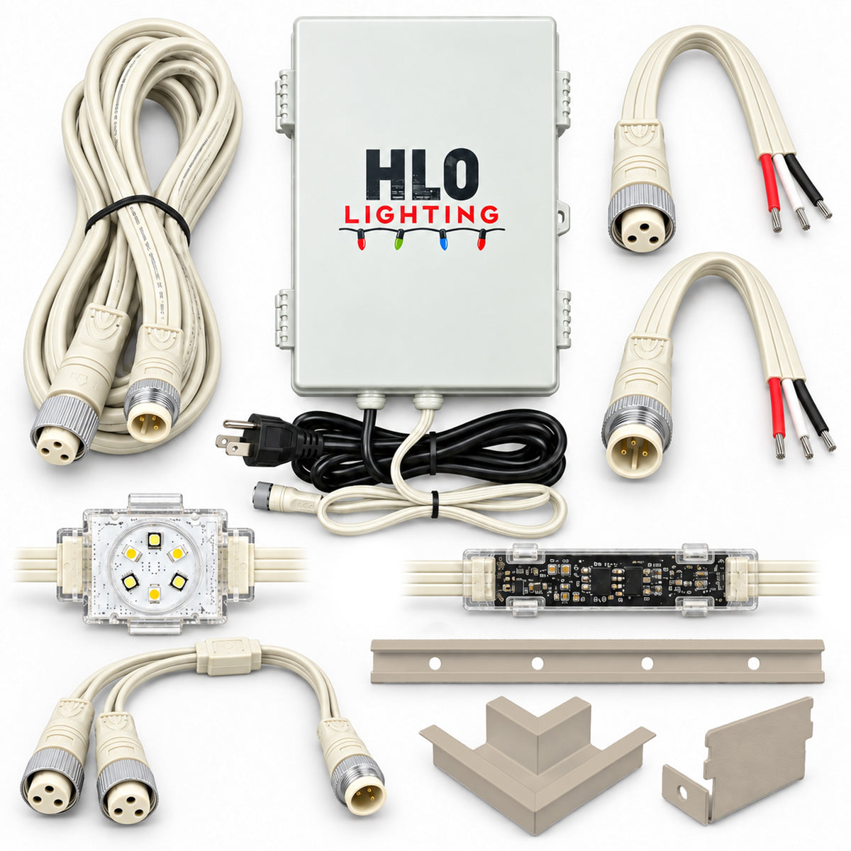
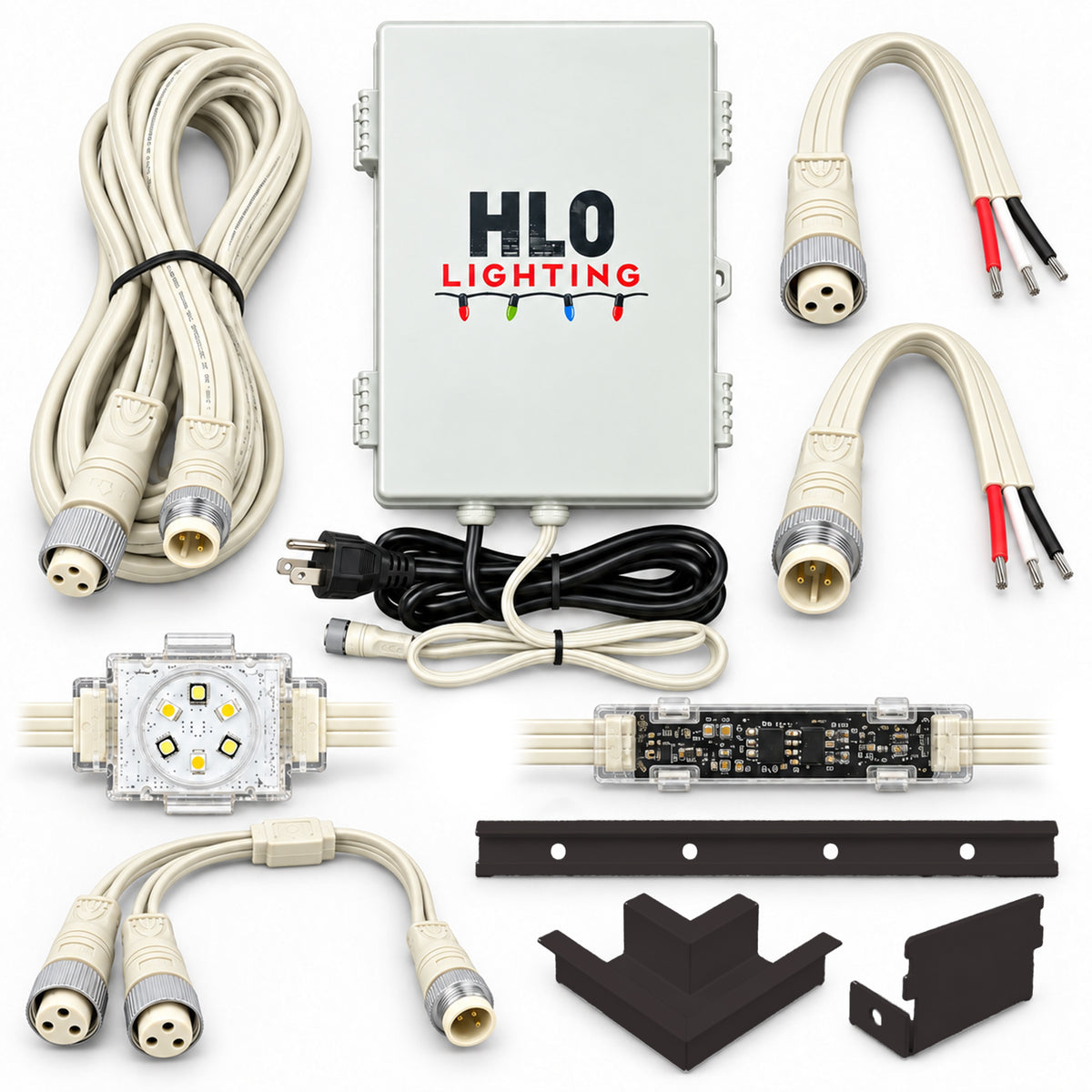
The HLO Permanent Lighting System Kit provides the core components needed to build a complete, professional permanent exterior lighting installation. The kit combines approximately 60 meters (197 ft) of aluminum track with 240 RGBW permanent lights, plus the controller, power supply, connectors, extension cables, corners, end caps, signal boosters, and accessories needed to adapt the system to real-world rooflines.

Each 48V light uses RGBW technology with a dedicated 3000K warm white, providing both full-color effects and a natural warm-white option. The system uses a serial 3-wire connection, with a standard spacing of four lights per meter.

The included 450W control box combines the power supply, timer, and smart controller with Bluetooth and Wi-Fi connectivity. Aluminum track sections provide a clean, finished mounting system and can be powder coated to coordinate with the home's trim or soffit.

The kit also includes extension cables, Y-connectors, male and female connector leads, and corner components to accommodate roofline transitions, dormers, gaps, and changes in direction. Three inline signal boosters are included for longer cable jumps; the manufacturer's specification recommends signal amplification when extension cable runs exceed approximately 10 meters (32.8 ft) to maintain stable control-signal transmission.

Kit Includes

  • 240 × 48V RGBW Permanent Lights — 3000K warm white, 1.3W per light
  • 60 × 1 m Aluminum Track Sections
  • 1 × 450W Control Box with Timer, Bluetooth & Wi-Fi Smart Controller
  • 4 × Track End Caps
  • 4 × 90° Corner Track Sections
  • 3 × Signal Boosters
  • 4 × 48V Y-Connectors
  • 4 × Male 48V Connector Leads
  • 4 × Female 48V Connector Leads
  • 4 × 1 m (3.3 ft) Extension Cords
  • 2 × 2 m (6.6 ft) Extension Cords
  • 1 × 3 m (9.8 ft) Extension Cord
  • 1 × 5 m (16.4 ft) Extension Cord

With the included track, wiring accessories, splitters, and signal-management components, the kit is designed to give installers flexibility when navigating multiple rooflines and architectural features while maintaining a clean, integrated finished appearance.

$1,999.99White

Plan the system

Permanent lighting details

Product Description

The HLO Permanent Lighting System Kit provides the core components needed to build a complete, professional permanent exterior lighting installation. The kit combines approximately 60 meters (197 ft) of aluminum track with 240 RGBW permanent lights, plus the controller, power supply, connectors, extension cables, corners, end caps, signal boosters, and accessories needed to adapt the system to real-world rooflines.

Each 48V light uses RGBW technology with a dedicated 3000K warm white, providing both full-color effects and a natural warm-white option. The system uses a serial 3-wire connection, with a standard spacing of four lights per meter.

The included 450W control box combines the power supply, timer, and smart controller with Bluetooth and Wi-Fi connectivity. Aluminum track sections provide a clean, finished mounting system and can be powder coated to coordinate with the home's trim or soffit.

The kit also includes extension cables, Y-connectors, male and female connector leads, and corner components to accommodate roofline transitions, dormers, gaps, and changes in direction. Three inline signal boosters are included for longer cable jumps; the manufacturer's specification recommends signal amplification when extension cable runs exceed approximately 10 meters (32.8 ft) to maintain stable control-signal transmission.

Kit Includes

  • 240 × 48V RGBW Permanent Lights — 3000K warm white, 1.3W per light
  • 60 × 1 m Aluminum Track Sections
  • 1 × 450W Control Box with Timer, Bluetooth & Wi-Fi Smart Controller
  • 4 × Track End Caps
  • 4 × 90° Corner Track Sections
  • 3 × Signal Boosters
  • 4 × 48V Y-Connectors
  • 4 × Male 48V Connector Leads
  • 4 × Female 48V Connector Leads
  • 4 × 1 m (3.3 ft) Extension Cords
  • 2 × 2 m (6.6 ft) Extension Cords
  • 1 × 3 m (9.8 ft) Extension Cord
  • 1 × 5 m (16.4 ft) Extension Cord

With the included track, wiring accessories, splitters, and signal-management components, the kit is designed to give installers flexibility when navigating multiple rooflines and architectural features while maintaining a clean, integrated finished appearance.

Plan it. Test it. Hide it.

Install your system with confidence

Choose your control-box route, work through each module, and print a clean field guide when you are ready to install.

48V systemUse the included HLO control box and compatible components.
Follow directionEvery light section must point away from the controller.
Boost long jumpsAdd a signal booster beyond 10 m / 32.8 ft without lights.
Test as you goVerify each major section before closing the track.
Your installation checklist0 of 10 modules complete

Before starting: Confirm the component quantities included with your selected kit and compare them with your route plan.

1 Plan the complete routeStart at the control box and map every roofline, split, gap, dormer, and ending point.

Walk the property before mounting anything. Mark the control-box location, first light, straight runs, peaks, gables, corners, dormers, changes in elevation, branch points, light-free transitions, and final end caps.

Control box→Lead cable→Y-connector↙︎ ↘︎Left and right runs
  • Measure illuminated rooflines and every light-free jump separately.
  • Choose accessible, protected locations for the controller and connections.
  • Plan transitions along soffits, fascia, corners, and trim—not across shingles.
  • Confirm where extensions, Y-connectors, boosters, corners, and end caps belong.

Installer mindset: follow the architecture, not the shortest visible line.

2 Bench-test the systemProve the controller, app, lights, and direction before climbing a ladder.

Connect the first components on the ground:

Control box→Lead cable→Lights→Lights
  • Controller powers on.
  • Lights illuminate and change color.
  • Warm white operates correctly.
  • The app responds to the controller.
  • Signal-direction markings point away from the controller.

Then disconnect power before beginning physical installation.

3 Get from the control box to the first lightChoose the path that matches the building and keep the entry clean.
Where will the control box be mounted?

Garage route: conceal it through an approved interior path

Control box→Garage→Attic→Soffit exit→First light
  1. Mount the control box in an accessible location near suitable power.
  2. Route the low-voltage lead toward the attic only when the cable and installation method are approved for that concealed space.
  3. Travel above the ceiling toward the desired starting roofline.
  4. Locate the underside of the eave from inside and outside before drilling.
  5. Bring the cable through a protected opening in the soffit near the first light.
  6. Leave only enough exposed cable for a relaxed, serviceable connection.
ShinglesThe finished roofing surface. Do not drill through, lift, or run loose lighting wire across it.
FasciaThe vertical finished roof edge, often behind the gutter.
SoffitThe underside of the overhang—the normal lighting location and a potential concealed exit when appropriate.

Exterior route: make the cable disappear into the trim

Control box→Protected exterior route→Trim / conduit→Soffit→First light
  1. Verify the control-box location follows its weather/exposure rating and applicable requirements.
  2. Choose a vertical corner, downspout line, trim return, or other discreet architectural path.
  3. Use an exterior-rated, appropriately sized conduit or color-matched wire-cover channel when the installation calls for one.
  4. Keep the cable supported, protected from sharp edges, and tight to the structure.
  5. Turn beneath the eave and meet the first lighting section from the soffit side.
  6. Keep connectors accessible and do not create tight bends, tension, or loose loops.

Cleaner result: match the wire cover to the home’s trim and place vertical travel on an inside corner whenever possible.

4 Mount the trackBuild a straight, consistent foundation before seating the lights.
  • Mount to a suitable surface beneath the soffit or approved mounting area.
  • Keep every track section straight and consistently spaced from the fascia.
  • Align neighboring sections before fully tightening fasteners.
  • Use fasteners appropriate for the mounting surface.
  • Locate wiring before every screw and keep it clear of sharp edges.
  • Use the 90° corner track instead of sharply bending a straight section.
5 Install lights in the correct directionDirection controls communication through the entire run.
Controller→Light 1→Light 2→Light 3→Next section
  • Locate the signal-direction marking before installing each section.
  • Keep every module oriented away from the controller or branch point.
  • Seat modules correctly in the track openings.
  • Tuck wire safely without pinching or puncturing it.
  • Fully seat each waterproof connector and tighten its locking collar.

Do not reverse a section. A reversed section can prevent everything downstream from communicating.

6 Connect and test every major sectionCatch a problem while the last connection is still within reach.
  1. With power disconnected, join the next section.
  2. Confirm the connector is fully seated and tighten the locking collar.
  3. Verify the cable has slack and is not stretched or pinched.
  4. Restore power and test the newly added section.
  5. Disconnect power again before continuing installation.

Fast troubleshooting: if the first lights work and the next section does not, inspect the connection between the last working light and first non-working light.

7 Move between rooflines, gables, and dormersHide transitions along the house and keep cable off the shingles.

Use an extension cable when the next illuminated section is separated by a dormer, upper roofline, gable, obstruction, or change in elevation.

1Inside or behind the soffit edge

Follow the underside of the eave whenever the structure and approved installation method allow it.

2Along fascia or trim returns

Use corners, seams, and vertical trim lines to move discreetly between elevations.

3Inside track or wire-cover channel

Use matching track or an exterior-rated, color-matched channel where appropriate.

Example: move from a lower roofline to a dormer

  1. End the lower lights near the closest architectural transition.
  2. Run the extension beneath the soffit or along trim.
  3. Follow a vertical inside corner or return upward.
  4. Bring the cable beneath the dormer.
  5. Connect to the first dormer light and continue in the correct direction.
Lower lights→Hidden extension→Dormer soffit→Dormer lights

Never lay loose cable across shingles. Loose cable is visible, can move or snag, collects debris, and receives unnecessary wear.

Can the cable pass through a soffit?

Only use a concealed soffit, attic, or building-space route when the cable and installation method are approved for that use. Do not drill blindly, block soffit ventilation, or allow cable to rub against an unprotected sharp opening.

Jump is 10 m / 32.8 ft or lessLights → Extension → Lights
Jump is longer than 10 m / 32.8 ftLights → Extension → Signal booster → Extension → Lights
8 Split the run when neededUse a Y-connector to start centrally or send lights up a gable.

A Y-connector turns one incoming run into two outgoing branches.

Incoming cable→Y-connector↙︎ ↘︎Branch A + Branch B
  • Start near the middle of a house and send one branch left and one right.
  • Continue the main roofline while another branch climbs a gable.
  • Keep both outgoing branches oriented away from the split.
  • Test both branches before closing their track.
9 Finish each run and test the complete systemSecure every ending, then walk the entire property.
  1. Secure the final track section and verify the last light.
  2. Protect the final connection and install the track end cap.
  3. Remove loose wire, unsupported loops, and cable tension.
  4. Power on and walk the complete system.
10 Troubleshoot safelyStart at the last working point and change one thing at a time.
Nothing turns on

Confirm the control box has power, the controller is on, the first connector is fully seated, and the first section points in the correct direction.

Lights stop after one point

Find the last working light. Inspect the next connector, direction marking, extension, and track section.

Lights are blue, static, or acting strangely

Check direction, input/output orientation, loose connections, controller configuration, and the configured light count in the app.

Lights flicker after a gap

Measure the light-free cable distance. Add a signal booster beyond approximately 10 m / 32.8 ft and inspect each extension connection.

The end of the run is dim or incorrect

Inspect connectors, extensions, wiring, and system configuration. Contact HLO before adding lights beyond the supplied kit or modifying the power system.

Safety closeout

  • Disconnect power before servicing components.
  • Never puncture modules or wiring.
  • Keep screws and sharp edges away from cable.
  • Fully tighten outdoor connectors.
  • Do not install in wet, icy, or unsafe conditions.
  • Use appropriate ladder and fall-safety practices.
  • Follow applicable electrical and building requirements.
  • Use a qualified electrical professional for line-voltage work, new receptacles, or circuit changes.

Expand or repair a system

Individual components

Shop compatible Permanent Lighting components individually.

Product quick view